
Came across the video below. Thought it was cool. Cooler to make one though right?! I found the original paper here, which has some great explanatory diagrams in. I thought I would start with modelling the gears.
Reference
K. Abe, K. Tadakuma and R. Tadakuma, “ABENICS: Active Ball Joint Mechanism With Three-DoF Based on Spherical Gear Meshings,” in IEEE Transactions on Robotics, doi: 10.1109/TRO.2021.3070124.
Autodesk Fusion 360
Have been playing with Fusion 360 on trial. I have previously used Inventor. I thought recreating these gears would be a good project to get into Fusion. Snapshots below should set you incorrect direction – and concepts are easy enough so could be repeated in Solidworks or Rhino or whatever.
BTW No idea if what I am doing is correct. Just a heads up.
2D sketch of spur gear
Fusion 360 comes with ‘demo’ script (actually two, a Pythino one and C++ one) for creating a spur gear component. Its in tools >> addins >> scripts (or SHIFT+S). I used this as starter for both the Cross Spherical Gear (CS-gear) and Monopole gear (MP-gear). When you run the script (I used the Python one) it presents you with a dialogue…this is where we start:
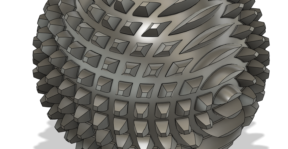
Cross-spherical gear
1. Spur gear script
NOTES:
- Set root fillet to zero since >0 slowed things down for me.
- We don’t need centre hole.

2. Rotation of component (Important!)
You need to rotate the gear component created ‘half a tooth’, so… 

3. Create base sketch
Create a sketch on the underside face of the gear component (which coincides with h global XY plane). Draw two orthogonal lines each crossing the gear through its centre (and global origin). Lines align with the global x and y axes respectivly.
The marked dims of the blue area are arbitrary. We use this to carve the cross cut in (5).
Once you have made your new sketch you can hide the spur gear component – we don’t need it anymore.

4. Solid revolution
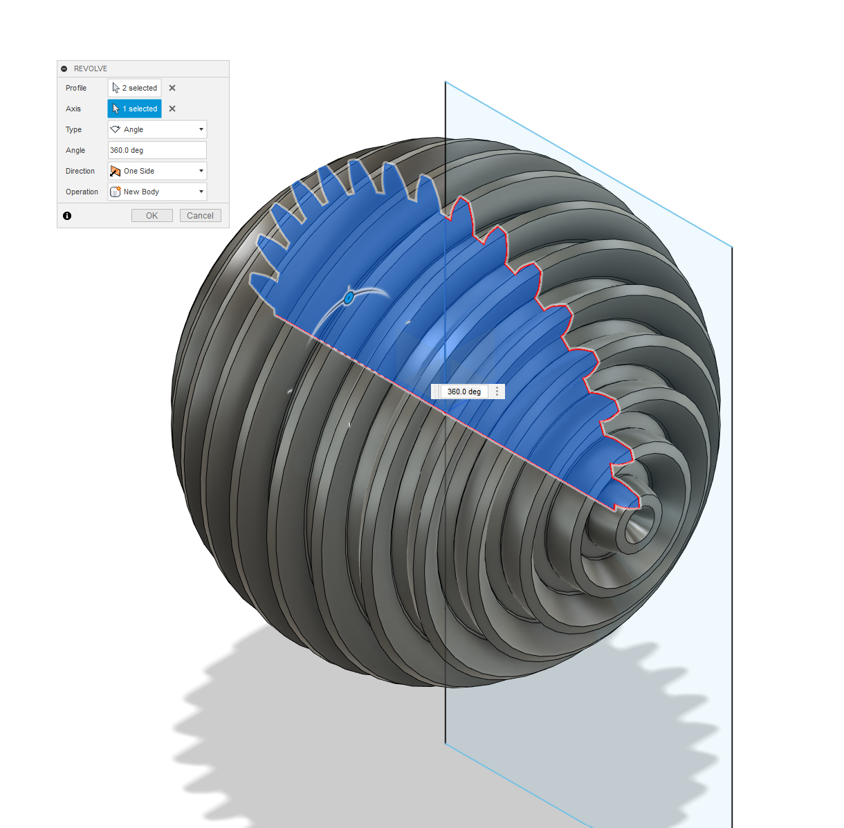
5. Cross cut (by solid revolution in cut mode)
This can cause thing to choke a little on computer (hence why we removed fillet in original spur gear)

Done
We have the basic form of the spherical gear now, I think. Needs a bit of work for prepping for 3D printing though: probably best sliced in two and printed in two halves. Plus a mounting point for whatever-we-what-to-move. Maybe for another post.

Monopole gear
I posted what I thought was the way to make the MP-gear, but have since deleted since was totally incorrect. Hope to post correct method in a future post, when I work it out!

Quite tricky – beyond my modelling skills, in Fusion 360 at least. Rhino & Grasshopper is beckoning, which does seem a bit of a cop-out, given my initial aim.